java sim.UI [exefile][exefile] is the filename of an executable in the Cebollita EXE format. The simulator's loader will load the text and data segments, set up the stack and global pointers appropriately, and jump to the entry point of the program.
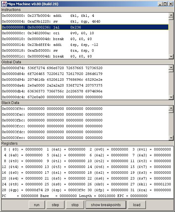
The window is split into four panes, which show, respectively:
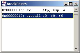
Each line shows the address and instruction at which a breakpoint was set. Clicking on a breakpoint will "seek" the instruction memory window to the address of the breakpoint.
java sim.Mips a.outTyping "help" will give a list of commands. Here's an overview of what's currently implemented:
| Command | Meaning |
|---|---|
| help | Dump a help message. |
| s | Step one instruction |
| r | Run the program |
| trace | Toggle tracing (be verbose) |
| show | Show the machine state |
| sb [addr] | Set a break at the given address |
| db [addr] | Delete a break at the given address |
| lb | List all breakpoints |
| rm [addr] | Read memory at [addr] |
| wm [addr] [value] | Write the memory at [addr] with the given [value] |
| lm [addr] [words] | List [words] of memory starting at [addr] |
| q | quit |
System mode: In this mode, the simulator actually manages many of the system services, namely system calls. A set of system calls is provided to perform basic IO, which is all simply handled in software. These are defined below. Beginning users will probably spend most of their time running the simulator in this (default) mode. Most of the details below need not worry them in that case.
Bare mode: In this mode, the simulator is given a "disk image" rather than an executable as an argument. Upon startup, the simulator's "BIOS" loads the OS loader (bootloader) from the given disk image. The bootloader must be able to fit in a single 512 byte block and run in a location independent manner. Its job is to load the OS into low memory. The OS is standard-looking executable and the bootloader can just slam it into memory starting at location zero. (Detail: the OS is linked as if it starts at location 20, because the top 5 words are always the executable descriptor -- the OS can reuse this space later, if it wishes. The OS should have its exception handling routines (trap handler) as the first thing in its text segment. The machine will automatically jump to location 20 on exceptions...) Once the kernel is loaded, the bootloader should jump to its entry point (as specified by the executable) and it's off to the races. In this mode, memory mapped IO is used, and it's the kernel's responsibility to provide system calls to read/write from these addresses to perform IO. If the kernel wishes to load/run other processes, it must manage the base & length registers accordingly to perform address translation for that process.
Memory mapped IO: By default, the machine has a single CharacterDevice, a single BlockDevice, and a single RAM. The ram is 64KB in size, by default. The Character device is connected at address 0x40000000 and the BlockDevice is connected at address 0x40000010. Details of the operation of these devices can be found elsewhere (currently in the JavaDoc). In bare mode, the user has to write code that uses these devices to do IO. In system mode, these devices are typically unused, in favor of doing IO through the system calls. However, depending on the IO interfaces provided to the user, student's can happily write their own memory mapped IO routines for system mode. (Specific documentation
Differences: The MULT and DIV instructions currently do not simulate the HI/LO registers as on a MIPS machine. MULT and DIV are encoded as normal R-type instructions, where the destination register takes the product (or quotient). Users wishing to implement modulus must do simulate the process in software.
R2000 Coprocessor 0: Simulates the coprocessor to some extent, with some differences from a real MIPS machine (base and length registers), the other 4 are the same. Currently reg 12 isn't used...
| Service | Number | Args | Result |
|---|---|---|---|
| print_int | 1 | $a0=integer | |
| print_string | 4 | $a0=string | |
| read_int | 5 | integer in $v0 | |
| read_string | 8 | $a0=buffer$a1=length | |
| exit | 10 |